A recent question about the resultant velocity of an airplane illustrates different ways to make a diagram showing the bearings of air velocity and wind velocity, and to work out angles without getting too dizzy.
Drawing a vector diagram
Here is the question, from Renata in late March:
Hello,
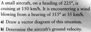
I am working on this question:
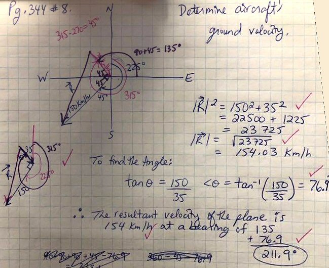
Here is my work:
I think I’ve done the work correctly but have a few questions.
#1 – Why / how do we know to choose the angle to solve as being between the wind vector and the resultant?
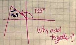
#2 – Once we get the angle of 76.9 degrees….it is an “outside” angle not starting at the origin, so I’m not understanding why we take 135 degrees and add the 76.9 degrees for our answer when those angles don’t even technically line up with e/o.
Thank you.
In fact, as we’ll see, the answer is correct. But Renata is wise to want to go a little deeper and understand how to think rightly about vector angles, in order to get it right the next time, and the next. As part of Polya’s problem solving method, I like to emphasize that the final step includes looking back at what you learned from a problem, and looking forward to how it can be used in future problems.
A systematic way to draw
Doctor Rick answered, emphasizing that there is more than one way:
Hi, Renata.
I got the same answer you did, but I did not choose the angle you chose — so the answer to question #1 could be, “We don’t.”
I also did not draw the diagram the way you did — but then, vectors don’t have a location; we can place them wherever we wish.
My diagram (cleaned up — I sketched it on paper originally) is attached. Let me share with you how I thought as I worked.
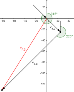
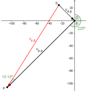
I like to label vectors in relative-velocity problems with subscripts to indicate “the velocity of ___ with respect to ___“. So the airspeed of the aircraft is labeled vp,a meaning “velocity of the plane with respect to the air”; the windspeed is “velocity of the air with respect to the ground”, va,g; and the ground velocity is “velocity of the plane with respect to the ground”, vp,g.
Doing this makes it easy to see which two vectors sum to the third:
vp,a + va,g = vp,g
where the second subscript of the first vector matches the first subscript of the second vector, and the “outer” subscripts of that pair become the subscripts of the resultant.
That is, the velocity of the plane with respect to the air, plus the velocity of the air with respect to the ground gives the velocity of the plane with respect to the ground.
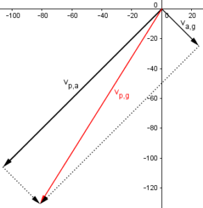
I drew the vectors with the summed vectors “head to tail” and the resultant completing the triangle. But the order of the summed vectors really doesn’t matter (addition is commutative).
The same sum of vectors could have been draw in the other order (wind first),
or in parallelogram form,
Renata’s version looked like this, with our labeling:
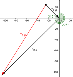
This appears odd to me, because the starting point of the resultant vector is not drawn at the origin, but it makes good sense as a routine method (which appears to be what was taught in this class) because the given directions are clearly visible. What’s important isn’t how you draw it, but whether you understand what you drew.
I have the bearings of the summed vectors marked; I don’t think you had any trouble with the fact that the wind blows from a bearing of 315°, so the bearing of the vector differs from that by 180°.
The bearing of \(v_{a,g}\) is opposite to the 315° angle specified, because the latter gives the direction from which the wind comes, which is opposite to the direction toward which it blows. So this is \(315-180=135°\).
Solving for bearing and speed
Now to actually solve the problem:
You recognized that vp,a and va,g are perpendicular, so we can use right-triangle trigonometry rather than the more complicated Law of Cosines and Law of Sines to find the magnitude and direction of vp,g. (Or maybe you haven’t gotten to those Laws yet.) You can choose to find either acute angle of the triangle. I chose to find the angle between vp,a and vp,g, because it is clear that I could subtract that angle from the bearing of vp,a to get the bearing of vp,g. I got 13.1° for my angle; if I rotate vp,a counterclockwise by that angle, I get the direction of vp,g. Counterclockwise rotation means subtraction of the angle, when working with bearings: 225° – 13.1° = 211.9°. (It would be the reverse when working with standard trigonometric angles, positive being counterclockwise.)
Why is it a right triangle?
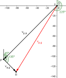
The bearing from P to O is \(225-180=45°\), and \(135-45=90°\).
Now, using the right triangle OPR, $$|OR| = \sqrt{|v_{a,g}|^2+|v_{p,a}|^2}=\sqrt{35^2+150^2}=\sqrt{23725}=154.03$$
$$\tan(\angle POR)=\frac{|v_{a,g}|}{|v_{p,a}|}=\frac{35}{150}=0.2333…\\ \angle POR=\arctan(0.2333…)=13.134°$$
The bearing of OR is \(225-13.134=211.866°\).
These answers agree with Renata’s.
Observe that he avoided the uncertainty about adding or subtracting the angle in the triangle by thinking ahead to that step and choosing the angle that would make it easiest! This is a common aspect of good problem-solving, which I call defensive driving: Always have your eyes on the road ahead!
But her method also works …
You did it differently, but you still got the correct answer. You must have known what you were doing, unless you knew the answer and just looked around for some calculation that would give that result — or maybe you were lucky. But it was valid, however it came about.
In my diagram, you found the angle between the heads of va,g and vp,g. We can see (in my figure) that if we swing va,g clockwise around that vertex by the angle you found, we should get the direction of vp,g. So we take the bearing of va,g, 135°, and add your 76.9° to it, obtaining 211.9°.
I hope this helps you understand how to think through these problems. If I have raised more questions in your mind, feel free to ask them.
We can see this addition of angles in Renata’s drawing, too, when we mark the two angles:
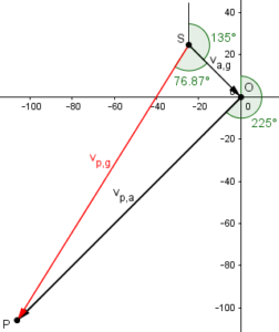
Clearly the bearing of the red resultant is \(135+76.87=211.87°\).
What do you do with a “bearing from”?
Renata replied,
Thanks a lot Dr. Rick. After looking through your answer several times I do understand how you approached the question. I think in the lesson the teacher was saying that if you have a bearing that is worded “from”, like “from a bearing of 315 degrees” like in this question, and the vector’s head is pointing toward the origin, that we do not want to leave the head at the origin, and therefore should extend the vector into the 4th quadrant and complete the diagram this way.
Am I right about that? Should we always redraw the diagram if the vector’s head is going toward the origin?
This sounds like what Doctor Rick did, and does seem helpful.
Doctor Rick responded,
You asked:
I think in the lesson the teacher was saying that if you have a bearing that is worded “from”, like “from a bearing of 315 degrees” like in this question, and the vector’s head is pointing toward the origin, that we do not want to leave the head at the origin, and therefore should extend the vector into the 4th quadrant and complete the diagram this way. Am I right about that? Should we always redraw the diagram if the vector’s head is going toward the origin?
It is not necessary even to have an origin in the figure. All that is required is to reverse the direction of the vector. That is, if you initially draw a vector pointing in the direction of bearing 315°, you then move the arrow to the opposite end to indicate a vector “from” that bearing.
After I have done this (likely in my head, but you can do it on paper), I then arrange the vectors (with their final directions) “head to tail” if you wish to use the triangle method for graphical vector addition. (You’d do it differently for the parallelogram method.) As I said, it doesn’t matter which vector’s tail meets the other’s head (as long as you chose the correct pair of vectors to add) because addition of vectors, like addition of numbers, is commutative.
If you want coordinate axes (so that it’s clear which direction is North for the sake of bearings), you can add them after drawing the triangle. I would put the origin at the tail of the first vector.
What two others did wrong
Renata wrote back a week later:
Hi Dr. Rick,
My friends and I have quite the debate over this question still. I have taken pictures of 2 of their work, where my friends have different final answers than I do. They swear theirs is correct and I can’t quite explain how it could be incorrect. Could you please explain how their answers are not 100% correct, if that is the case?
Thanks!!
A:
B:
Doctor Rick answered,
Hi, Renata.
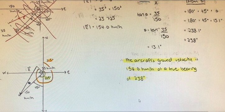
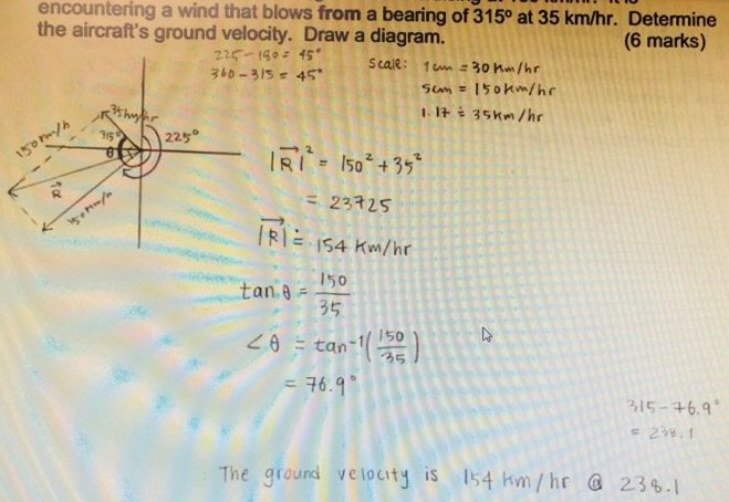
You can see what each person did differently, right? Looking first at the second image, it’s really obvious: this friend has the wind blowing in the opposite direction — toward a bearing of 315° rather than from that direction. Have you pointed this out to your friend? How does he/she justify that choice of direction?
Interestingly, this one’s answer for the speed, 154 km/hr, is correct, but the bearing is wrong. In effect, this friend found the wrong diagonal of the parallelogram – but since it is a rectangle, they are equal, and just go in different directions! All they missed was the reversal of the “from” vector.
The first image has a more subtle error: the angle of 13.1° was added to the heading of the aircraft, where in the work I showed you, I subtracted the 13.1° from 225°. You solved it a different way, and it’s harder to compare this person’s work with yours since you found a different angle.
This friend’s diagram looks the same as yours, and I gather that this is exactly the way you have been taught to make the figure — not the way I said I would do it. So in explaining what’s wrong, it would be best to stick with that established method. However, I am not sure what you may have been taught about deciding whether to add or subtract an angle. One thing you might do could be called “graphical common sense“. We look at the figure and see that R is pointed more to the south than the vector on the other side of angle θ — closer to 180°. That means we want the bearing of R to be less than the heading of the aircraft — therefore subtract.
Here again is our version of B’s picture (with our labeling), which is essentially the same as Renata’s:
They correctly found the angle at the bottom to be 13.1°, just as Doctor Rick did in a different but congruent triangle; but it is a little harder to see what to do with that angle than in his approach. The red vector is what they called R (the resultant); we want a bearing that is “backed up” a bit from the bearing of the airspeed vector, which is why we subtract the angle. You can imagine swinging a vector around through 225° clockwise to OP, then tacking the arrowhead down at P and swinging the tail counterclockwise through 13.13° to line up with SP.
If a more concrete explanation is needed, you could make a copy (a parallel translation) of the vector R, putting its “tail” at the origin. You could then point out that the angle between the aircraft windspeed vector and this copied vector (call it R’) is equal to the angle θ because they are alternate interior angles. In the figure I am picturing, it’s clear that we subtract θ from the aircraft heading of 225°.
This approach in effect makes Doctor Rick’s triangle, in which it is obvious we should subtract the angle:
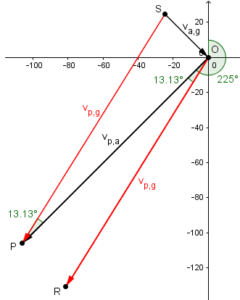
Looking at point O, it is clear that OR is at bearing \(225-13.13=211.87°\).